Sunday 29 June 2014

A QRO HF DUMMY LOAD

image 16

100ohm power resistors for use in Wilkinson power splitters are often available at low cost. A pair of these resistors will make an excellent dummy load. I recently acquired a power film resistor which has four 50ohm resistors mounted on a large copper heatsink flange. As all of the resistors are connected to the mounting flange at one end, it was not possible to connect the resistors in a series/parallel combination to make 50ohm. The solution was to connect the four resistors in parallel to make a 12.5ohm load and use a 4:1 transmission line transformer to provide a 50ohm match. The transformer consists of two turns of RG58 on a Maplin N90AB ferrite core. This gives a perfect 1:1 SWR from 1.8 - 30MHz. The finished circuit is in Figure 6. Note that the DC voltage from the diode is only half the peak-input voltage because of the 2:1 voltage ratio of the transformer. I haven't been able to make much of an impression on this load during testing. Several minutes of SSB speech at 500W PEP will bring it from room temperature to lukewarm. I'm sure my transmitter would catch fire long before this load gets hot!

Saturday 28 June 2014

5W 14MHz (20m) AM Transmitter


This is a simple audio transmitter for the 14MHz (20m) band. Its principle is seen from the diagram, so I will describe very briefly: The first stage is a simplified oscillator, the other three stages are amplifiers. The coils are wound on the 4mm diameter core with screw ferrite core to fine tune to the highest brightness of the light bulb. As a modulation choke, a secondary of small transformers (eg 220V/9V) is used. The tuning capacitor is also tuned for the highest brightness of the bulb. Then you can replace the bulb by a short. When you connect other antennas However, it is necessary to re-tune the output. Never operate without antenna!! Current consumption of the transmitter from the 12V supply during the normal operation of about 800mA. The coils have 30, 25 and 12 turns.


5W 14MHz (20m) AM Transmitter schematic

Homebrew Antenna Tuner


Steve Yates - AA5TB

Tuner Schematic


For years I've thrown together simple antenna tuners to get me on the air when needed. Whenever I would go to a sidewalk sale or hamfest I would pick up any components that might someday come in handy to make an antenna tuner. Commercial antenna tuners are very expensive and often of questionable quality. They are so very simple to make that I find it hard to justify purchasing a store bought unit. I realize that good antenna tuner components can be quite expensive when purchased new if you are even lucky enough to find a supplier. If you are not in a hurry all of the necessary components can be found used for very reasonable prices.

There is nothing special about the antenna tuner described on this page. It is a simple T-network and I have found that it can match any unbalanced antenna system I've ever put on it. I've always used PI-networks but component values can become unwieldy at the lower frequencies for such a network. Below are some more photos of my T-network.

Front View
Front View

Rear View
Rear View

Inside View
Inside View

The components were all found on the surplus market and even though it looks very old it's really only a few years old. The metal enclosure is probably 50 years old even though it had never been used when I purchased it at a sidewalk sale. The roller inductor is silver plated and incorporates a very good turns counter. It is WWII surplus and I had been saving it ever since I came across it as a kid. The two capacitors are 500 pF each and I removed them out of a defunct automatic antenna tuner that was once used at a shore station for ship to shore communications. I purchased all of the insulators from a local surplus outlet. Even the knobs and dial plates are ancient surplus. After all is said and done, I have about $10 invested in this tuner but to purchase one of similar quality the price would probably be about $300.

I don't have plans for you to follow in order to replicate this antenna tuner but as you can see via the schematic it is very simple. I would suggest obtaining the components first and then design everything around them. Use short, fat conductors if possible to interconnect the components. Ther required capacitor plate spacing is determined by the transmitter power and the impedances involved. For 100 W or less the plate spacing of most available air-variable capacitors is probably adequate. The capacitors that I used here have a maximum capacitance value of 500pF each but I probably could have gotten by with 250 pF units. For the inductor try for around 25 µH if you plan to use the tuner on 80 m and maybe 160 m. The larger the inductor's conductor, the better. If you can't find a roller inductor then a tapped inductor can easily be made assuming an adequate switch can be obtained. Of course for simple open-air designs, a wire and alligator clip will suffice.

If the power you plan on using is at QRP levels, say less then 5 W, then the components can be greatly reduced in size. The polyvaricons that are often found in less expensive AM radios can be used for the capacitors and a small tapped coil wound on a toroid will suffice for the inductor. It should be noted however, that the efficiency of this antenna tuner is inversely related to the losses in the inductor. Therefore, even though a small inductor will not burn up at QRP levels, a dB of loss is a dB of loss at any power. What I am getting at is that at some impedance ratios, the RF currents in the coil can become relatively high. In these cases the losses within the inductor can become high unless care is taken to keep the Q of the coil high. This can be done by making the inductor out of the largest conductor possible and by making sure any contact resistance, such as the alligator clip, is kept at a minimum. It should be noted however, that this contact resistance will usually swamp out the RF resistance of the conductor. In other words, if you are using an el cheapo alligator clip or tap switch, there isn't too much sense in going to a 00 AWG conductor ;-)

I only created this page to hopefully encourage others to try and build their own antenna tuners instead spending good ham radio budget on an expensive commercial tuner. I apologize for not having exact instructions but this is an easy project to do on your own with the components that you have available.

40 Meter QRPp Transmitter


Steve Yates - AA5TB

40m QRPp Transmitter


I built this simple, crystal controlled 40 meter CW transmitter back in 1996. It sports full break-in operation and 250 mW of output power. The final output transistor is a mighty 2N2219A. The N6WG QSL card laying against the lid is just an example of one of the many contacts I have made with this transmitter. The station was located in California and my antenna was an inverted L (bent monopole) operated against a very poor ground system (a couple of ground rods). Considering the losses in my antenna system, I thought the contact was pretty good.

My design was based on one of the late Doug DeMaw's (W1FB) designs with many of my own modifications. The rig is built into an old file box I bought at a garage sale for $1.00.s

Inside View
Inside View

Schematic Diagram

Friday 27 June 2014

SSB signal generated by phase shift


SSB signal generated by phase shift
Home SSB transmitter is a challenge to the HAM and a test to its own power. But up to now little HAM can self-make SSB transmitter, the main reason is the core components of the transmitter SSB-crystal filter and the matching crystal (such as crystal filters are equipped with 9MHz the 8998.5kHz, 9001.5kHz crystal) is difficult to purchase in the country, in this case, the phase shift method can generate SSB signals, comparing with the commonly used filter, but it has the advantages of easy make, low-cost, particularly the output frequency of VFO (should have a very high degree of frequency stability) can be directly taken as the firing frequency, it does not have to go through one or more frequency, greatly simplifying the whole circuit , the circuit is shown as the chart.

Wednesday 25 June 2014

The Moxon-Beam


The Moxon-Beam was introduced by L. Moxon (G6XN) in his book "HF Antennas for all Locations" (RSGB- Publications, Great Britain 1993). This beam is a 2-Element-Yagi with radiator and reflector and reduced size to about 75% of a normal beam. The 2-Element-Yagi with reflector has normally a 0,2-lambda-boom and an impedance of 50 W. The Moxon-beam has a 0,18-lambda-boom and still 50 Ohm. This is a good impedance for wire- beams.The ends of the two elements are bended backward (radiator) or forward (reflector) and act as a capacitive load. That is much better than inductive loading with coils. So we have greater bandwidth and lower losses.Through the reduced size we get a 0,5-0,7 dB lower gain than with a fullsize beam.

This type of a 2-Element-Yagi has an unbelievable F/B-ratio on the design frequency of >= 30 dB. That is higher than with any other 2-Element-Beam.

The gain is higher on the beginning of the band and lower at the end. The bandwidth for a SWR < 1,5 is great enough for the range of 28,0-28,7 and 21,0-21,45 MHz if the beam is built up with aluminium tubes. Wire-beams of the Moxon-type have a smaller bandwidth.

The design frequency should be for a frequency 1/3 from the beginning of the band, because the SWR raises more below the design frequency. For example look for the SWR of a tube-Moxon for the 15-m-band:

Designing a Moxon- Beam is very easy with a useful little program by D. Maguire, AC6LA with the name "Moxgen".

This freeware can be downloaded at:

www.qsl.net/ac6la/

Moxgen generates an output file for "EZNEC" for modifications (e.g tapering) and shows you the dimensions for  building a wire-Moxon.

http://www.qsl.net/dk7zb/Moxon/Moxon.htm

Tuesday 24 June 2014

ADRIAN KNOTT PROPOSES TUNED VLF ACTIVE ANTENNA


Hi to all! Today I found a very interesting project that using a small whip for hear the long VLF waves. Adrian Knot says that with this simple and inexpensive system you have good results, but suggests the using outdoor far from electric sources.
References: (http://www.hard-core-dx.com/nordicdx/antenna/special/vlfactive.html)

Friday 20 June 2014

Experimenting with Colpitts Oscillators


Most of the RF circuits we have discussed to date are based on crystal oscillators.  Crystals provide excellent stability in an oscillator circuit, but are limited to a single operating frequency (or a limited frequency set).  Luckily, crystal oscillators aren't the only game in town.  In fact, many types of oscillator circuits exist, including a popular variation; the Colpitts Oscillator, named after its inventor Edwin H. Colpitts.
The Colpitts oscillator is an LC oscillator, meaning that it generates its resonant frequency through an inductor (L) and capacitor (C) tank circuit.
colpitts LC tank circuit
The tank circuit oscillates as voltage charges C1 and C2 and is discharged through L1, driven by a single transistor.  I found this YouTube video, which shows an animation of current as it moves through the circuit, which may be helpful to visualize how the circuit works.

Many variations of the colpitts oscillator exist, but all have this LC tank circuit in common.  The beauty of this design is that is can be scaled for any frequency, by changing the L and C values.

I experimented with several variations to present a simple but practical design for the 40 meters radio band.  The two most important factors that were considered were: 1) frequency stability, 2) a clean sinusoidal waveform.  This design generally meets these two requirements.
buffered colpitts oscillator schematic
The optional variable capacitors C7 and C8 are used to fine tune the output frequency.  C7 will give you tighter control over the frequency, while C8 will give you a wider tuning range.  The RFC or RF choke is an inductor that connects voltage to the circuit but isolates the DC voltage from the oscillator circuit.  For the RFC I used 26 turns on a T50-2 toroid.  For L1 I used 17 turns on a T50-6 toroid.  Q1 is an 2n3052 (preferably heatsinked).  Q2 is a 2n3904.
This particular design includes a buffered output.  This is important to the overall stability of the circuit.  Since the colpitts is a Voltage Controlled Oscillator (VCO), anything inside the circuit that would alter the voltage will also affect the frequency generated.  The output buffer allows you to add additional stages to the circuit without affecting the oscillator stage.

Likewise, the circuit is using +12v DC.  Other input voltages can be used, and so can other transistors, but both will affect the frequency output.

Here is the circuit on a breadboard, and its waveform:

colpitts oscillator on breadboard
colpitts oscilloscope waveform
And this is what it looks like after I soldered it up:

colpitts oscillator circuit

colpitts oscillator waveform

In general, it's a terrible idea to construct RF circuits on a breadboard.  As you can see, my output waveform is cleaner on the breadboard as opposed to the circuit, because I modeled the circuit on the breadboard.  RF circuits do not perform well on breadboards (although HF circuits do OK), because of the parasitic capacitance created by the conductor rows.  But, if you are just having fun like me, a breadboard is a simple way to prototype and the results aren't too far off, and a low pass filter will clean up the waveform.
Also, you will see that the frequency output differs between the breadboard and the soldered version.  Again, this is due to the extra capacitance added by the breadboard.  But, this is simple to overcome; add additional capacitance to C1 and C2 or increase windings on L1 to lower the frequency (or decrease windings to increase the frequency).
Try it out yourself and see what values work.  Change the input voltage and transistors to suit your needs or available parts.
Additional reading:
> http://www.learnabout-electronics.org/Oscillators/osc23.php
> http://www.electronics-tutorials.ws/oscillator/colpitts.html

Half-watt AM transmitter


"The Poppet" is a half-watt AM transmitter designed by Mr. Doug Gibson of England. The original design was published in issue 84 of SPRAT, newsletter of the GQRP Club. The version shown here incorporates changes suggested by Steve Hartley and others.

Although it was designed to work with a microphone and to be used in the 160 meter band (1800-2000 kHz), the Poppet can easily be modified to work in the 1600-1720 kHz end of the AM broadcast band and work with a line level input from a mixer instead of a microphone.

Construction details are not critical. The LM386 and the output transistor will need heatsinks. The circuit can be built "dead bug style" with the modulator chip stuck upside-down to the copper circuit board for heatsinking.

[schematic diagram]

parts list

C1, C2, C13: 0.5 uF
C3: 1 nF (1000 pF)
C4, C5: 10 uF electrolytic
C6: 10 nF (.01 uF)
C7, C15: 100 nF (.1 uF)
C8, C16: 330 pF
C9: 50 pF variable
C10: 200 pF
C11, C12: 1n8 (1800 pF)
C14: 68 pF
C17: 220 pF
D1: 1N4148
D2: 9 volt zener
J1: microphone jack
J2: RF output jack
L1: 60 turns, 38 SWG wire, T37-2 core
L2: 50 turns, 38 SWG wire, T37-2 core
R1: 560 K
R2: 4700 ohms
R3: 1K trimpot (mic. gain adjust)
R4: 270 K
R5: 100 K
R6: 560 ohms
R7: 33 K
R8: 5600 ohms
R9: 100 ohms

Q1, Q3: BC109 (possible equivalents: NTE123A, 2N2222A)
Q2: 2N3819 or similar
Q4: BFY51 (possible equivalents: NTE128, 2N3053)
RFC1: 10 turns of small enameled wire on ferrite bead
RFC2: 1 mH, rated for 500 milliamps
T1: 12 turns primary, 2 turns sec. on half-inch binocular ferrite core

To modify the Poppet for neighborhood broadcasting in the 1600-1720 kHz frequency range, either increase the capacitance of C8 to bring the VFO's frequency down into the broadcast band, or replace the VFO with a simple crystal oscillator or PLL synthesizer. The microphone pre-amp stage can be omitted if the unit is used with a line-level audio source such as a mixer or tape player.

Code Practice Oscillator


Here is a simple Morse Code Practice Oscillator using LMC555 or LM555. It generates an audio tone while pressing the Morse key. Frequency of oscillation can be found using following equation, f = 1.44 / [(R1 + 2R2) C], approximately 800Hz for the given values and setting R2 at center

Morse code practice oscillator

NSH Field Strength Meter


N S Harisankar/VU3NSH

A well tuned antenna system works like a dummy load, i.e. the SWR is 1.2:1 or below but the hunting range is low. What's wrong? Insufficient radiation? How to know that? Yes, this is what the article about. You can measure the effective radiation using a field strength meter (FSM). A commercial FSM can measure the loss or gain of radiation, testing polarisation, plot the radiation pattern for the various antennas for comparison. The cost for a commercial FSM can vary from Rs 1500/- to Rs 5000. But this design one can assemble for a few hundred.

Analog FSM and NSH FSM
Figure 1. Analog FSM and NSH FSM

The Standard Analog Meters or LCD - DVM based FSM are some what “DEAF” and the meter level movement can’t be read from a distance of around 5 ft and above. To avoid this problem, this FSM is having a 10 level multi coloured 3mm LEDs for level reading; this will give a fair reading up to 20 ft + distance even at night.

The FSM will give RF radiation reading; picked through the air, that shows an antenna’s gain of radiation. Due to this REAL READING, one can compare different types of antennas gain, angle of radiation, polarization etc. The FSM sniffs out bad coax, connectors or improperly grounded transmitter. It is a good instrument to plot radiation patterns of yagis / verticals. It is an educational tool for studies. SWR meter cannot do or detect some measurements about RF. But this FSM will do!.

When Working with different types of input RF signal levels, the sensitivity of the NSH FSM can be controlled by changing different types of sensing antennas. Remember that, VSWR meter only shows that the antenna is fully loading and shows a low reflected power or very low SWR, but it does not mean that the antenna is efficiently radiating the TX power into AIR - The only tool that shows the exact on-air radiation levels is FSM.

This FSM is designed to work on 2 meter (144 - 146 MHz) . A tuned L-C circuit at input is used to make the FSM selective for the desired band. The heart of this circuit is LM3915 dot/bar display driver from National Semiconductors, providing a logarithmic 3dB/step analog display. Disconnecting 1C1 pin 9 from +ve supply, changes the display from a bar graph to a moving dot display, hence reducing the total power consumption. In bar graph mode, up to 100mA may be drawn from the battery when all LEDs are on. The FSM can be powered by a 9V(6F22) battery.

The inductor L1 consists of 2.5 turns of 22 SWG enamelled copper wire, and the internal diameter is 7mm and air core. The two transistors forms a high gain amplifiers and the output voltage is depends on the resistor selected (L, M, H) by the sensitivity selector S1.

The circuit should be installed in a metal box. Three LEDs of green, three LEDs of yellow, three LEDs of orange and finally two LEDs of red are arranged in increasing order for the field strength levels. The highest level of LED is wired to pin 10 and lowest level LED is wired to pin 1 of IC1.

Field Strength Meter - Schematic
Figure 2. Circuit diagram of NSH FSM. (Originally published in Elektor Electronics, December 2000 edition. Copyright Elektor International Media, www.elektor.com)

For tuning this FSM, connect the rubber flux antenna to the input of the FSM, and kept vertical. Select 145 MHz in the hand held, select 500 mW and, set up and try FSM at reasonable distance. Key the transceiver and read the segment. If it is full increase the distance between, till one or two LED to glow. Then trim C1 for getting more LED to lit. LED brightness can be adjusted by P1 if necessary.

1 inch whip, 6 inch whip, 19.25 inches (quarter lambda) or diamond RH3, RH10 can be used as input sensing antennas for this FSM.

NSH FSM - Applications
Figure 3. NSH FSM - Applications

dummy load, i.e. the SWR is 1.2:1 or below but the hunting range is low. What's wrong? Insufficient radiation? How to know that? Yes, this is what the article about. You can measure the effective radiation using a field strength meter (FSM). A commercial FSM can measure the loss or gain of radiation, testing polarisation, plot the radiation pattern for the various antennas for comparison. The cost for a commercial FSM can vary from Rs 1500/- to Rs 5000. But this design one can assemble for a few hundred.

Analog FSM and NSH FSM
Figure 1. Analog FSM and NSH FSM

The Standard Analog Meters or LCD - DVM based FSM are some what “DEAF” and the meter level movement can’t be read from a distance of around 5 ft and above. To avoid this problem, this FSM is having a 10 level multi coloured 3mm LEDs for level reading; this will give a fair reading up to 20 ft + distance even at night.

The FSM will give RF radiation reading; picked through the air, that shows an antenna’s gain of radiation. Due to this REAL READING, one can compare different types of antennas gain, angle of radiation, polarization etc. The FSM sniffs out bad coax, connectors or improperly grounded transmitter. It is a good instrument to plot radiation patterns of yagis / verticals. It is an educational tool for studies. SWR meter cannot do or detect some measurements about RF. But this FSM will do!.

When Working with different types of input RF signal levels, the sensitivity of the NSH FSM can be controlled by changing different types of sensing antennas. Remember that, VSWR meter only shows that the antenna is fully loading and shows a low reflected power or very low SWR, but it does not mean that the antenna is efficiently radiating the TX power into AIR - The only tool that shows the exact on-air radiation levels is FSM.

This FSM is designed to work on 2 meter (144 - 146 MHz) . A tuned L-C circuit at input is used to make the FSM selective for the desired band. The heart of this circuit is LM3915 dot/bar display driver from National Semiconductors, providing a logarithmic 3dB/step analog display. Disconnecting 1C1 pin 9 from +ve supply, changes the display from a bar graph to a moving dot display, hence reducing the total power consumption. In bar graph mode, up to 100mA may be drawn from the battery when all LEDs are on. The FSM can be powered by a 9V(6F22) battery.

The inductor L1 consists of 2.5 turns of 22 SWG enamelled copper wire, and the internal diameter is 7mm and air core. The two transistors forms a high gain amplifiers and the output voltage is depends on the resistor selected (L, M, H) by the sensitivity selector S1.

The circuit should be installed in a metal box. Three LEDs of green, three LEDs of yellow, three LEDs of orange and finally two LEDs of red are arranged in increasing order for the field strength levels. The highest level of LED is wired to pin 10 and lowest level LED is wired to pin 1 of IC1.

Field Strength Meter - Schematic
Figure 2. Circuit diagram of NSH FSM. (Originally published in Elektor Electronics, December 2000 edition. Copyright Elektor International Media, www.elektor.com)

For tuning this FSM, connect the rubber flux antenna to the input of the FSM, and kept vertical. Select 145 MHz in the hand held, select 500 mW and, set up and try FSM at reasonable distance. Key the transceiver and read the segment. If it is full increase the distance between, till one or two LED to glow. Then trim C1 for getting more LED to lit. LED brightness can be adjusted by P1 if necessary.

1 inch whip, 6 inch whip, 19.25 inches (quarter lambda) or diamond RH3, RH10 can be used as input sensing antennas for this FSM.

NSH FSM - Applications
Figure 3. NSH FSM - Applications

FM Radio Rectangle Super Gainer (Moxon Antenna)

N. S. Harisankar / VU3NSH
Tel : +91 491 2576102, 9895741932

It is not much popular antenna but much old design!! The original name of this antenna is Two Element Driven Arrays. In 1952 Les Moxon published this Genius Design in QST July Issue. It is a rectangular shaped two elements with a closed spacing of 0.18 lambda. The ends of the two element are folded in 90 degree face to face with a critical spacing of each other. This rectangle beam is popular among ham radio operators as Moxon Antenna. Few hams are using it for HF (SW) bands. It is a directional type antenna with a wide angle of 136 degree typical aperture and with a very good band width. (The Radiation pattern is like Kidney shape, and it is the same in reciprocity) . Due to the bend at the ends of each element and due to the critical spacing of each tips it is a capacity loaded, and it yields the wide bandwidth and low SWR levels. It is a low take of angle type of 14 degree or low typically, and it pick ups maximum stations from planes. Therefore I decided to make this antenna in FM Radio band to receive the spectrum of 88 MHz to 108 MHz.

One of my SWL Murali (School Teacher), who is a good listener of MW-SW-FM bands, asked to make an antenna which gives directivity, wide angle and very high gain for his own use. For this purpose I converted the basic design to 3 meter BC band radio use. I made this rectangle beam (Moxon) with 3/8 th aluminum tube. For the critical spacing of each element tips, I made hilum insulators as a prototype. The feed point is connected with a simple cable TV connector called F-Connector which is economical and easily available at the local market.

While testing, if it is pointing to eastern direction it will pick the signals from East and also it will pick the signal from South East and North East due to its wide angle aperture. More over the beauty of this antenna is the two elements will give 9 dBi + gain. Typically this antenna gives 7 to 14 dBi depending upto the accuracy of the construction and it can be a wide angle of 100 degrees to 136 degrees, the F/B ratio can be 30 dB to 40 dB. This antenna should be mounted at least 1 lambda of the operating frequency above the ground level. i.e., 3 meter (10 ft). For excellent performance, the height should be 25 to 30 ft. and the surrounding clearance should be maximum. Do not test this antenna near to any metallic objects and that will reduce its performance drastically.

For receiving FM BC Bands you can connect any good quality and low loss 75 ohms coaxial cable to the driven elements at the middle point of this antenna. No matching is required like balun, gamma, hair pin etc. and therefore no question of matching loss. Refer the following figures for getting specific ideas about the antenna and its construction. A well constructed rectangle beam antenna is equivalent to a four element yagi antenna.

In the next part we will reveal some antenna engineering about rectangle beam for 2 metre ham band operation.

FM bc band - mesurements for 100 Mhz
Fig. 1. FM bc band - mesurements for 100 Mhz. This measurements are for 3/8 Aluminium tube (9.5 mm OD)

FM bc band - mesurements for 100 Mhz
Fig. 2. Rectangle beam (Moxon) plot

QRP Fan Dipole


Fan Dipole Circuit The object of the exercise was to produce an aerial that would allow me to operate from 40 metres to 10 metres, specifically 40, 20, 17, 15 & 10 metres. The antenna was always going to be mounted in the attic as no external antennas are permitted at my QTH, the attic allows the antenna to 'beam' roughly northwest / southeast and the house is some 40 feet above sea level. Construction would be simplified by the fact that I intended to run a maximum of 10 watts which means that the antenna wires can be simply attached to the rafters. (Click on images for a larger version.)

http://www.radiowymsey.org/FanDipole/fandiploe.htm

Vertical antenna


vantenna

This type of antenna exhibits an omni-directional pattern, with a low radiation angle. The length of the radiator is calculated by using the formula 234/Frequency in Mhz, for feet, or 71.5/Frequency in Mhz, for meters to make a 1/4 wavelength, at the desired frequency. The radiator can be made entirely from 1" aluminum tubing, but can also be made from several sections of tubing of different sizes (Below 20M it is not appropriate to use 1" tubing). These could be fastened together using pipe clamps, after splitting the lower section about 1", across the circumference, along the diameter to facilitate clamping of the upper section.

The radiator is mounted on a reasonable length square wooden post which is buried in the ground or fastened to the roof. Large diameter pipe clamps are used to fasten the radiator to the wooden pole. At about 1/2" from the base of the radiator a hole 1/8" should be drilled into the aluminum pipe. This hole is used for a bolt onto which the coax center conductor is fastened.

The radials should be slightly longer than the radiator. To facilitate multi-band operation at least four radials should be used for each band you wish to operate in, the radiator being cut for the lowest band. All the radials are then fastened, or soldered together, and a connection is made to the coax cable shield. The radials should be buried a few inches into the ground, and ideally spread out in a circle. An antenna matching unit is used for multi-band operation. Alternatively, in place of aluminum tubing, a PVC pipe could be used, with a 1/4 wavelength wire positioned inside as the radiator. Note: For this antenna the Antenna Matching Unit should be at the base of the antenna, for best performance, and can be remotely controlled.

A Tree Friendly 2 Meter Halo Antenna


Having purchased an all-mode, all-band (160m - 70cm) transceiver, I became curious about what 2-meter weak signal operations have to offer. I have a 5/8th over 5/8th vertical collinear antenna hanging in a tree at some 30 odd feet high, but I never heard anything on it, except on FM. The reason for that, I learned, is most 2-meter weak signal operations take place using horizontal polarization. Cross polarization is good for about 20 dB attenuation, which easily translates into the difference between perfectly good copy and inaudible signals. So I decided I needed a horizontal polarized antenna.

As is usually the case with antennas, there are a bazillion designs to choose from and none of them really fulfills all your requirements. I do not have a mast or tower, and I love to use trees for supports, so I wanted something that I could hang from a tree branch. Since I have no means to rotate the antenna, I required that the new antenna have an omnidirectional radiation pattern. It didn't have to be the best performer, because I just wanted to get my feet wet in this new mode of operation. There are few designs that would fit that bill. I settled on the Halo antenna because of its small footprint. This is important because larger designs would require a longer branch, with sufficient clearance in all directions, to hang from. The Halo I describe here has a diameter of only about 12 inches and can be hung virtually anywhere in a tree.

The Halo Antenna

Halo stands for "HAlf wave LOop". The antenna is in fact nothing else but a half wavelength dipole with the legs bent in the shape of a circle. However, the ends do not meet, (especially near the end of the month) so technically it's not a loop. This loop can be fed with coaxial cable using a gamma match.

The Halo is certainly not a new design. Laurence M. Leeds and Marvel W. Scheldorf obtained a patent for this antenna in 1943. You can find their design at the U.S. Patent Office under Patent Number 2324462. Click on the "Images"-button to view the patent. You'll need a special browser plugin to access the patent. See the U.S. Patent Office website for more information on this.

Most Halo designs you find on the internet have moving parts. Often they require some sort of tuning capacitor and have a capacitor in the gamma match along with a slider construction that connects the gamma arm to the radiator. I prefer a design without moving parts so that the antenna doesn't get detuned easily when a bird decides the antenna makes a good resting place. I found the design that I describe here in a German antenna book "Antennen Buch" by Karl Rothammel, Y21BK.

Basic Design

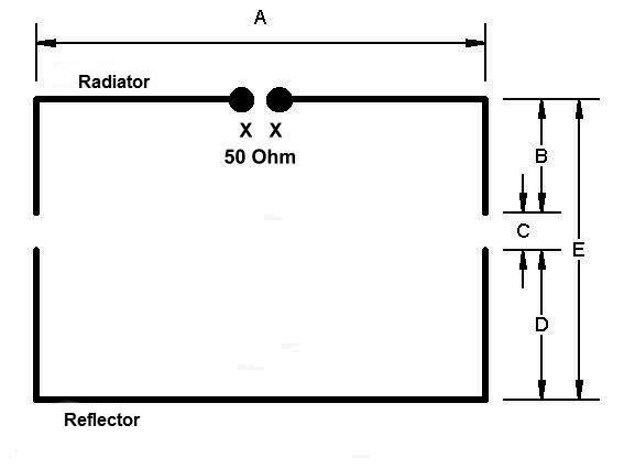
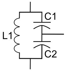
The design of this antenna is very simple and straightforward. It basically consists of a half wavelength piece of copper tubing bent into a circle. Between the ends of the tube there needs to be a gap of at least 1 3/16". This is to minimize capacitive coupling between the ends. This antenna is fed by a coax feed line through a gamma match. The gamma match is constructed from 6 1/4" #4 or #6 copper wire. This wire is bent into an L shape. The short end of the wire is soldered on the inside of the loop at the point where the long end of the gamma arm aligns with the halfway point of the loop. See below:

2mbasic

You could feed the loop directly with 50 ohm coaxial cable as shown above. However, I added a 1:1 current balun (choke) to the original design. I did this to force all the RF current, on the inside of the braid of the coax feed line, to go into the antenna and not to come back down on the feed line on the outside of the coax braid. This will help keep the feed line from radiating, causing potential RFI problems and changing the radiation pattern of the antenna.

Building the Halo

Building this antenna is like making the pieces of the puzzle first, and then putting the puzzle together. First you build the antenna itself, then the support boom, the choke balun, the mount, and finally, you put these parts together.

The Antenna

Start out by cutting a string to a length of 41 inches. You'll use this to measure the correct tube length. Thick monofilament wire as used for garden trimmers works very well. Mark this wire at the halfway point. A piece of electrical tape will do fine. This is the point where you’ll later have to mark the copper tube and where the coax braid will get soldered to the tube.

You'll probably find the soft copper tubing material in a 10-foot length, coiled up in a bag. Fortunately, the coil diameter is about the same diameter as the final loop will be. So there will be very little bending involved to get the circle shape needed for the loop. Eyeball how much tube you'll need from the loop coil and cut it. Don't attempt to make an exact measurement yet. In fact, the measurement I give here for the main loop is deliberately somewhat too large anyhow. Put the part you cut off on a flat surface and now measure how much you really need using the string from the previous paragraph. Cut off the excess tubing. Use the string again to find the halfway point of the tubing and mark it. This will be the point at which you will later solder the coax braid. Make sure the tubing is shaped like a circle, and that the ends are at least 1 3/16" apart. To keep the ends apart, I cut a piece of hexagonal Bic pen tubing to length and put it between the ends. You can secure it with some shrink tubing, but don't shrink it until you're done with the final tuning later on.

2mhalo3

Now build the gamma from a piece of #6 or #4 copper wire. Use the measurements from the detail diagram above and bend it as shown. Solder the short end of the gamma arm to the inside of the loop at the point where the long end of the gamma arm lines up with the halfway point on the main loop (as marked earlier).

The Support Boom

To support the antenna, I used a piece of 3/4" schedule 40 PVC pipe. Lay the antenna on the pipe and cut it so it's just a bit longer than the diameter of the loop. Now drill holes through the pipe to mount the antenna. On one end of the pipe you need two holes approximately 1 15/16" apart for the main loop and the gamma match to go through. Make sure you drill the hole for the tube very close to the end of the PVC pipe. This will make it easier to solder the coax braid onto the copper tube. Also be careful not to drill the hole for the gamma match all the way through the pipe. The gamma match only goes in halfway through the pipe and will not come out the other side.

On the other side of the PVC pipe, drill a hole in the same plane as the first two holes for the piece of plastic tubing (hexagonal Bic pen) that is being used to keep the ends of the main loop apart. Next, drill the holes necessary to mount the SO-239 (panel mount) connector.

The last hole you need to drill is for mounting purposes. This hole needs to be drilled in the middle of the PVC pipe, all the way through. Make absolutely sure that this hole is perpendicular to the plane of the antenna. This hole needs to be the size of a bamboo skewer you can buy at the grocery store (sold in a bag of 20 or so). This skewer is later used to mount the antenna. You can use something else if you like as long as it's thin, strong, sturdy and straight.

2mhboom

The Balun

Even though the original design does not call for a balun, I decided to add a 1:1 current balun in order to prevent RF currents from flowing back onto the outside of the coax braid, perhaps causing the feed line to radiate, create interference and change the radiation pattern of the antenna. The balun I built for this antenna consists of 12, 1/2" long, type 43 ferrite beads that slide over a short piece of RG-58 coax with the outer jacket removed. The hole in the beads I used was not big enough for the coax to slide through with the outer jacket intact.

The length of the piece of coax needed for the choke can be measured from the end of the boom where the gamma match is to the farthest edge of the SO-239 connector, plus about 3/4". The balun itself is about 6 inches long. If you use a different size of beads, just make sure you have enough beads to make a 6-inch long balun. You can secure the beads with some shrink tubing or electrical tape. This should be enough to make an effective balun for VHF that can handle up to 100 Watts of power.

One side of the coax should be prepared so you can solder it to the SO-239 connector. You can already solder the connector to the coax if you wish. The other side needs to be prepared so that the braid will reach the middle of the loop, and the center conductor meets the gamma match. Do not cut the center conductor to length. Instead, only remove the insulation from the center conductor so that it can be soldered later to the gamma match. Leave the excess wire intact. Put some shrink tubing or electrical tape around the braid to insulate it, except for the very end, of course.

If you do not have any ferrite beads available, you can construct an air core choke balun instead. There are several ways to make one. One method is to wind about 7 turns of the feed line on a coil form made from 3/4" PVC pipe. Place this choke near the antenna. If you prefer the choke to be part of the antenna, then you can wind 7 turns of the coax going from the SO-239 connector to the gamma match around the PVC boom.

The Mount

Since I've chosen to hang this halo from a tree branch, I needed to find a way to mount this antenna onto a rope coming down from a branch in such a way that the antenna itself will remain in the horizontal plane. I came up with a method that will use gravity to hold the antenna perfectly horizontal.

When you built the PVC boom, you drilled a hole in the middle for a skewer. Now imagine you put the skewer through the boom, put the support rope alongside of the skewer and then tie the rope to the skewer with some wire ties. If you'd hold just the rope above the skewer and boom, the boom would just dangle in all kinds of directions and stay far from being horizontal. However, if you'd make a small loop in the bottom end of the rope and hang a weight from it, you'll see that the boom stays perfectly horizontal. See the diagram below.

2msupport

Putting It All Together

Take a piece of pen tubing, or whatever you chose to fill the gap in the main loop, and push it in the PVC boom.

Next you can join the antenna with the boom. Take one end of the antenna and guide it through the hole next to the hole for the gamma match in the PVC boom. Slowly move the tubing through the PVC support pipe. You'll notice some resistance because the loop is round and the holes through the pipe are in a straight line. This causes some friction. With a small amount of force you'll see that that the tube will go through the pipe quite easily. Stop when you reach the gamma match. Do not push the gamma match into its hole in the boom yet.

Bend the end of the braid of the coax that goes inside the boom at a 90-degree angle. Just over 1/4" from the end should be sufficient. This will make it easier later on when you solder the braid to the tube. Also bend the exposed center conductor at a 90-degree angle about 1/4" from the end.

Slide the coax inside the PVC boom through the hole for the SO-239 connector. While you do this make sure that the end of the center conductor kind of scrapes on the inside wall of the pipe, on the side where the hole for the gamma match is located. At some point you'll notice that the wire will get caught in this hole. Pull the wire through the hole with needle nose pliers while you continue to slide the coax inside the pipe. Stop when the insulation around the center conductor appears at or through the hole. If you bend the wire a bit at this point, it will stay in place.

Solder the center conductor to the gamma arm. You can cut off the excess wire, but I simply bent the remaining wire along the gamma match. Or, wind it around the gamma match, just in case you have to do it again. Now slowly push the gamma arm in the hole of the PVC boom. If it doesn't quite fit, you can cut a tiny wedge out of the hole where the center conductor passes through the hole. Stop when the gamma match reaches the middle of the pipe and the center marking on the copper tubing is in the middle of the PVC pipe.

When you look into the pipe you'll see the braid near the copper tube on the inside of the pipe. Pre-tin the copper tubing at the halfway mark. Make sure this mark is in the middle of the pipe. Now you can solder the braid to the tube.

front

If you haven't already soldered the SO-239 connector to the coax, then do so now. Push the remaining coax into the boom and fasten the SO-239 connector to the boom.

Slide a piece of shrink tubing over each end of the antenna. Mate each end of the copper tube with the piece of pen tubing protruding from the support boom and slide the shrink tubing back a bit so it covers the piece of plastic tubing also. Do not heat the shrink tubing yet. This will hold the ends in place. You can also use electrical tape to do this. Just make sure the ends of the copper tubing stay flush with the plastic tube.

rear

Mounting the antenna

The antenna is now finished and we're ready to mount it for testing and tuning. Find a place where you can hang the support rope, like a tree branch. Make sure that there are no metal objects nearby, as they will detune the antenna. You can tune the antenna at a different place than the final destination if you wish.

Put a wire tie just below the middle of the skewer. This will prevent the antenna from sliding down the skewer. Secure the bottom half of the skewer onto the rope with two or three small wire ties. Make sure the skewer cannot slide along the rope. Drop the bottom end of the rope through the loop of the antenna and push the skewer all the way through the support boom from the bottom up. You may have to wiggle it a little bit when you're halfway into the pipe in order to get past the coax inside. Once the skewer is all the way through the support boom and the boom is resting on the wire tie on the middle of the skewer, you can fasten the top half of the skewer to the rope with two or three wire ties.

mount

Your antenna can now dangle freely from the rope. You'll see that the antenna does not really stay horizontal yet.

Make a small loop at the bottom end of the support rope and hang a weight from it. I used a brick. Even if the antenna is going to be mounted very high up in a tree, try to keep the weight near ground level. This serves two purposes. First, if for some reason the weight would fall, it will not fall on top of someone and no one will run into it. Second, it will keep the whole system very stable in the wind. If the weight would be higher than just a few feet of the ground, the wind would catch it also and start swaying the weight. Not only is this dangerous, it will also take a long time before the system is stable again once the wind drops.

Of course you could opt not to use a weight and simply tie the bottom of the rope down. However, that makes the whole mechanical system very inflexible. The rope would move back and forth over the branch when it's swaying in the wind, and eventually the branch might be cut.

If you later find that the rope and weight are swaying too much, you can minimize this with a guide rope that is tied to, say, a post, or the trunk of the tree, and goes around the support rope. The guide rope will then allow the support rope to move mainly in the vertical direction.

Once finished, the antenna should look something like this:

completed

Testing and Tuning

Before you test the antenna, double check you made all the right connections. When you use an ohmmeter to check the connections, you should be measuring a short (zero ohm resistance) between the center and outer connections of the SO-239 connector. This antenna is what is called "DC grounded", which may help reducing static buildup on the antenna.

Now you can attach a 50-ohm coaxial feed line to the antenna to test and tune it. Use a wire tie to attach the feed line to the skewer. This will make the feed line run along the support rope and help stabilize the system. If you plan on weatherproofing the antenna, then read the part on weatherproofing below first before you tune the antenna.

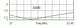
I borrowed an antenna analyzer to tune the antenna, but you can also do it with just an SWR meter. When you use an SWR meter and cannot find a near 1:1 SWR anywhere in the 2 meter band, you need to make note of three SWR measurements. One at 144 MHz, one at 146 MHz and one at 148 MHz. If you find that the SWR is lower at 144 than at 146 and 148 MHz, then you know the antenna is tuned below the 2-meter band. If you find that the SWR is lower at 148 than at 146 and 144 MHz, then you know the antenna is tuned above the 2-meter band.

You will probably find that the antenna is tuned somewhat below the 2 meter band. I deliberately listed the measurement of the main loop slightly too large which results in a lower than desired resonance frequency. Cut a tiny bit of each end of the copper loop until your antenna resonates near 144.200 MHz. That is the SSB calling frequency in the U.S.A. Of course you'll have to decide at which frequency you want the antenna to be resonant. The 1:1.5 SWR bandwidth of the antenna is about 1 MHz.

Since the gamma match is fixed, you will probably not be able to get an exact 1:1 SWR reading. More realistic is 1:1.1 to 1:1.3. Don’t let this scare you. SWR readings other than 1:1 are perfectly fine as long as they do not go much higher than 1:1.5. At that point many rigs will throttle back the power. If you really cannot sleep peacefully if the SWR isn't perfectly flat, then by all means desolder the gamma match from the loop and solder it at a different point until you've found that serene 1:1 SWR spot. I will warn you though that things can get messy real quick while it really isn't worth the effort.

If you find yourself in the position where you cut too much of the antenna ends in order to find that elusive 1:1 SWR, don't panic! There's an easy solution. Solder a half inch or so piece of solid copper wire (#14 will do) to the inside of each tube end as shown in second diagram on this page. The wire ends protruding from the copper tubing will fit inside the plastic separator tube. This will help maintain a clean look of the antenna while you get a second chance at tuning the antenna. Now simply cut small pieces, like 1/16" or so each time, off of each wire until the antenna resonates at the desired frequency.

When the antenna is tuned you can heat up the shrink tubing around the copper tube ends so that everything remains in place.

Weather Proofing

You can weather proof the antenna by filling all holes and gaps with RTV, or silicone sealant. Care should be taken when you want to seal the end of the boom where the ends of the loop meet. Putting RTV in that side of the pipe will detune the antenna. Make sure the sealant only goes to the inside of the PVC tube, and don't be tempted to put any sealant on the loop ends. The reason for this is that there is some stray capacitance between the loop ends. By adding sealant you change the dielectric between the tube ends, and therefore the value of the stray capacitance. This in turn changes the resonant frequency of the antenna. So it is better to seal this end of the support boom first before tuning the antenna if you plan on weather proofing the antenna.

If you feel that you need to seal the area around the small piece of spreader tubing, then use something like a very thin layer of nail polish. Also, if you want to make the loop very shiny, use some very fine steel wool to polish it.

Conclusion

I described how you can build a Halo antenna for two meters that does not require a mast, has a very low part count and can easily be built with a minimum of tools. This project description may seem more complex than similar ones you can find on the internet, but that is simply because most other plans leave out a great deal of detail, especially in the area of construction. I like to include the lessons I learned along the way when I built the antenna.

This article also described a unique way to mount these types of antennas on a rope. This makes the antenna an attractive alternative for use in the field where the usual support structures may not be available or for those folks who, like me, do not have a tower or mast. Of course you can mount the antenna on a mast with a U-bolt if you wish.

I have built a 2 and 6 meter version of this antenna, mounted them on the same support rope and feed them with separate feed lines.

2n6

The 2 meter Halo is mounted at 24 feet, and the 6 meter Halo is mounted at 20 feet high. As you can see, the Halo makes for a stealthy antenna even though that was never one of the design goals. If you really want the antenna to blend in with the background, paint it light gray or light green, and add some random black strokes here and there. When you break up any symmetrical lines and patterns, any object can be made invisible against the background.

These Halo antennas allow me to dabble a bit in VHF weak signal operations given the restrictions mentioned in the beginning of this article. While the performance of this type of antenna is limited compared to other types of antennas, I'm rather surprised with the DX contacts I’ve been able to make with a modest 50 Watts of power.

If you have any questions or suggestions, please do not hesitate to drop me an email.

73,
--Alex, KR1ST

Thursday 19 June 2014

TOBACCO TIN TRANSMITTER


I would like to show you my novelty transmitter project which I have enclosed into a tobacco tin. It requires very few parts, they are very easy to obtain, most of them came from my junk box with the exception of the crystal (7.030 MHz) which is an international QRP calling frequency. Any crystal will do as long as the operating frequency is within the amateur band, preferably in the CW section.

CIRCUIT

This is a one transistor crystal controlled transmitter, it uses the 2N2222 transistor in a basic oscillator arrangement, and has a simple output filter section for any unwanted harmonics. If the output filter was not used  the transmitted frequency would not only be 7.030 MHz but also 14.060 and 28.120 MHz etc. These unwanted frequencies are called harmonics. The output power is only 250 milliwatts (quarter of a watt) but high harmonic output is illegal even at this low power.  

CONSTRUCTION

I have used the ugly style construction, this is where you start with an off cut of copper clad board material, and build the circuit on the copper side up. The copper surface makes a low impedance ground and a anchor point for components. The grounded or copper surfaced components make a good solid support for the rest of the circuit to be built on. It is up to you as the builder which style you use, but the ugly construction is a lot cheaper than buying expensive vero board or making a printed circuit board. As you can see from the diagram there are very few parts, and it is straight forward to build. RFC1 is 6 turns of 32 s.w.g. enameled copper wire wound on a tiny ferrite bead, any thin wire and ferrite bead should work. The toroid in the output filter section is 14 turns of 26 s.w.g enameled copper wire wound around a T50-2 core.

OPERATING

When you have finished just press your morse key, no tune up procedure is necessary. You will also need an HF receiver, or shortwave radio with a BFO to operate with, I use a Realistic DX-394 receiver with an indoor wire and the transmitter next to the receiver with any of my outdoor antennas, but you could operate both from one antenna with a changeover switch. Although the transmitter only has 250 miliwatts this circuit when connected to a good outdoor antenna such as a dipole in favorable conditions has worked DX over 7000 miles. You will notice I have left a space on the right hand side of the box, this is to put an optional PP3 9 volt battery inside if I am going portable.

OTHER BANDS

The transmitter can also be  built to work on 80, 30 and 20 meters with the crystal of your choice, and the following changes=

80 meters =T50-2 toroid 21 turns capacitors 1, 2 and 3 =750 pfd

30 meters = T50-2 toroid 13 turns capacitors 1,2 and 3 =330pfd

20 meters =T50-2 toroid 12 turns capacitors  1, 2 and 3=270pfd

Please note It is illegal to operate this transmitter without an hf license.

Happy building and good DX M0DAD.

http://users.whsmithnet.co.uk/m0dad/construcion/tobacco_tin_transmitter.htm

THE PIPPIN QRP TRANSMITTER


Basically, it is a conventional Colpitt type crystal oscillator but with the output taken from a low value collector load resistor and direct coupling is made into the base of the PNP device used as an amplifier. The result is a circuit even more simple than the OXO and with considerable advantages.

The small amount of forward bias developed for the PA stage makes it very much easier to drive but is less than the voltage required to actually bias the stage "ON". Keying is in the emitter circuit of the oscillator stage and when the key is up and no current is being drawn there is no forward bias at all on the PA stages.

The isolation of the PA from the oscillator by taking the drive from the low value oscillator collector load, is most impressive and there is virtually no pulling of the oscillator even if the PA load is briefly shorted to ground.

Input to the PA stage runs at 120 to 150mA. at 12 to 14 volts and output on 7Mhz runs at better than 1 watt measured into a 50 ohm load. The PA transistor has a "Stove Pipe" heat sink attached and has been left running continously for more than 1 hour without any complaint from the PA stage.The collector choke is the usual type and uses 6 turns of 29 swg on two ferrite beads in tandem.

http://www.qsl.net/g3pto/pippin.html

The NOGAnaut QRP Transmitter


The crystal oscillator is the simplest form of transmitter. Normally, oscillators are used to drive buffer amplifiers and power amplifiers, which provide increased output, as well as prevent the output circuit from adversely loading the oscillator.

Most transistors exhibit a characteristic impedance different from the 50-ohm impedance of a well-tuned antenna system. An improper match between the impedance of the transistor and the load (e.g. antenna system) can cause severe power degradation, and worse, can seriously affect the signal, including shifting the oscillator frequency in unpredictable ways.

In the NOGAnaut transmitter, the 2N2222A transistor, which exhibits a characteristic impedance of approximately 200 ohms, is matched to a 50-ohm load via the pi-network filter composed of C1, C2 and L2. The values of these components were chosen to provide a close match between the 200-ohm transistor and a 50-ohm antenna (it is therefore critical that a good 50-ohm antenna system be used with this transmitter). It so happens that these values also form the familiar half-wave harmonic filter, thus satisfying FCC spurious emissions requirements.

NOGAnaut Schematic

Figure 1. NOGAnaut 80M Transmitter Schematic.

Capacitor C5 provides the necessary feedback to begin oscillation. You may find that you can operate your NOGAnaut without this capacitor--stray capacitance in the circuit provides a certain amout of feedback without C5. However, it was found during development of this circuit that the oscillator can have troubles starting at times, therefore it is recommended that you leave C5 in the circuit.

The 0.01 uF capactor, C3, serves as a DC-blocking capactor. At 3.6864 MHz, this capacitor is essentially a dead-short to RF, but blocks the DC current from flowing into the load.

This is a familiar Colpitts oscillator, operated in "common-base mode." The usual base-bypass capacitor is replaced by the capacitance of the crystal. With a 15V supply, this transmitter has been measured to deliver as much as 134 milliwatts into a perfectly matched 50-ohm load ("your mileage may vary"). With a 9V supply, about 20-50 milliwatts should be expected.

The transmitter is keyed by interrupting the positive supply voltage. You can modify this to be grounded keying, if necessary (just interrupt the negative supply voltage instead of the positive voltage). This may be necessary if you use a keyer that expects grounded or negative keying.

For a very good description of crystal oscillators, check out Solid State Design for the Radio Amateur by Wes Hayward, W7ZOI, and Doug DeMaw, W1FB. This is one of the most popular amateur radio books ever written and is packed full of practical information about how solid state circuits behave. It is published by the ARRL, and can be purchased directly from them, as well as from many electronics retailers.

Further information about pi-network filters can be found in The ARRL Electronics Data Book, by Doug DeMaw, W1FB, also published by the ARRL. This book contains most of the nuts and bolts of basic circuit design, and is a must for any ham shack.

http://www.nogaqrp.org/projects/noganaut/circuitdescription.html

25 part transmitter for the QRP Minimal Art Session


My Minimal-Art-Session rig shown here was made for class B of theQRP-MAS competition which is in May every year. In class B the transmitter should have a maximum of 50 components, and the fewer the number of components, the more points one will get per contact. With such simple rigs, only CW is viable.

This rig was made by combining ideas from several designs that I had seen and it was finished the same day as the competition. I ended up with 22 components in the transmitter except for the output filter. The rules say that no matter what, the output filter counts as three components. I guess this is in order that no one is tempted to simplify the filter too much and start emitting harmonics. 

It was made directly on two experimental boards. The right-hand one is for the VXO and the PA and the left-hand board contains the output filter. The transmitter is housed in an enclosure which once was a network converter. The advantage was that there already was a BNC-connector and a power supply plug there. All the original surface mounted components were blown off with a hot air gun so that the original board could be used as a base for my boards.

QRP-MAS transmitter for 80 m with 25 parts, drawing by LA4YW, Liv

My transmitter is made to give as close as possible to the maximum power of 5 Watts, but I ended with 3.5 Watts even though the IRF510 is capable of more. But there was not enough drive signal for that. I also had some problems with high frequency oscillations so therefore there is a series resistor to the gate and some extra decoupling which raise the component count. The transmitter frequency can be pulled about 1 kHz for each crystal. I have used it with an antenna tuner and a 75 m horizontal loop and with my Elecraft K2 as receiver. Antenna switching was manual.  

I didn't really count on many contacts because I only had crystals for 3579 kHz, not for the QRP-frequency 3560 kHz. But surprisingly I had 6 contacts with D (Germany) and one each with ON (Belgium) and OK (Czech republic). The "best" rig component-wise that I contacted was DK0VLP with only 12 parts.

Next time I plan to make a tube transmitter - inspired by the AA8V/W8EXI One-Tube Transmitter - hopefully cutting the component count in two myself also.

Homebrewed Off-Center Fed Dipole


Ocfd.jpg

Building A Homebrewed Off-Center Fed Dipole Scanner Antenna.

Aluminum/copper tubing construction:

You will need to check the fit of the tubing with the T connector and the caps while you are at the store. One combination that fits nicely is 3/4" copper pipe with 3/4" CPVC fittings (not to be confused with 3/4" PVC fittings which will be too large). The tubing/connector is held in place with 2 stainless steel sheet metal screws for connecting the balun to each element.

Find a "U" bolt to fit your mast. Drill two holes in the support pipe to fit the U bolt.The support pipe is 18" from the "T" to the mast.

Remember, bandwidth increases as diameter of the elements increases. I think, if I remember correctly, at the hardware store, that a few CPVC fittings will fit copper tubing perfectly!

Some say that the 18" element on top mounted works best,Some like the 48" element on top.It does'nt matter,it works the same.

If you use the copper tubing,be sure to paint it with some good,non-conductive paint.I used to paint mine light grey. -Have fun! (Teraycoda)

For an alternate/temporary mounting option, drill a hole in one of the end caps and put in an eye bolt with a nut on the underside of the cap to secure. Be sure to secure this end cap to the copper tubing somehow, perhaps with an additional small stainless sheet metal screw. Be sure that the eye bolt itself doesn't make electrical contact with the tubing. Also, drill a small weep hole in the bottom end cap to allow any moisture to escape that may accumulate inside. Use the eye bolt and some rope to pulley the antenna up high in a tree, or use a hook to hang it somewhere. Give careful consideration to safety and grounding depending on your particular usage scenario. (Qdude)


Variation for Off-Center Fed Dipole Using Simple Wire and 75 to 300 ohm TV Balun Transformer

Offset dipole scanner antenna.jpg

Electrically, this version is the same as the one using copper tubing (above) but can be assembled quickly and is quite portable. While not as broadbanded as an OCFD using copper tubing or other metal with a larger diameter, the OCFD made from simple wire turns in great receive performance in all the commonly scanned bands, as reported here on RR in multiple message threads.

The legs/ends of the dipole are simple bell wire and shown here coiled up. Uncoil them and hang them vertically; doesn't matter if the long or short leg is at the top... works the same either way. The wire terminal lugs shown at the end of the legs of the dipole antenna should NOT be connected electrically to the wires - just crimp them on over the wire insulation. They are used as convenient hangers for the antenna, and not meant for electrical connection. Obviously, the lugs at the TV transformer/balun ends of the wire should be stripped before crimping on the terminal lugs to ensure contact with the antenna wires when you attach the TV transformer. Ensure the 75 ohm coax feedline that you connect from the balun/transformer runs away from the antenna at as near a 90 degree angle as possible.