Thursday, 10 March 2011

2-BAND VFO FOR 80 AND 40 METERS

This project assumes you have built a functioning Simplest Ham Receiver and can solder components to a circuit board. Adapted from a schematic diagram in the 1993 ARRL Handbook, this VFO permits continuous user-selected tuning-range portions of about 50kHz on the 40 meter band and 30kHz on 80 meters. There are MANY designs possible, but this one was chosen because:

-- it uses the same power supply as the receiver (6-8V);

-- it demonstrates use of bipolar transistors as varactor diodes, which enables a simple cheap potentiometer to be used for tuning instead of a hard-to-find and probably expensive variable capacitor;

-- frequency range is easily changed by merely adjusting slugs on coils;

-- instead of two bands, covering larger portions of a single band is easily done; and

-- it's buildable and it works.

Decimal capacitance values are in microfarads (uF); whole-number capacitance values are in picofarads (pF or uuF).

Most general-purpose transistors will probably work in this circuit instead of those shown; back-to-back diodes can of course be tried instead of the 2N3053's.

L1: 4.6-8.5 uH adjustable RF coil (Miller #23A686RPC).
L2: 2.4-4.1 uH adjustable RF coil (Miller #23A336RPC). Miller #23A226RPC will also work.
Above coils are available from Circuit Specialists; another option that works well for L1 is the Miller #4204 5-12uH Adjustable RF Choke available from Ocean State Electronics. See Suppliers.
S1: DPDT miniature toggle switch.

Construction and Operation: First breadboard the circuit on a prototyping board to make sure it functions properly before soldering. Place the breadboarded (unsoldered) VFO in close physical proximity to the receiver, turn on the receiver, attach a mid-band-of-interest 80-meter crystal to the receiver's oscillator and tune the receiver to 80 meters. Apply power to the VFO and adjust its 80-meter coil slug until a loud signal is heard. Adjust slug to zero-beat the signal when the VFO's tuning pot is at mid-position . Make sure the VFO's switch is set for the right band! Check the VFO's tuning range by using crystal frequencies at either side of mid-band in the receiver's oscillator section. The range should be about 30 kHz.

Repeat calibration procedure for the 40-meter band - tuning range should be about 50kHz. To make a VFO that covers larger segments of just a single band, use two adjustable coils and capacitors of the same values for that band (or switch the coils between one appropriate capacitance for that band), then tune each coil for the appropriate band segment.

When the breadboarded VFO is working on both bands, go ahead and solder it together on a small experimenter's circuit board. (If you feel confident, skip the protoboard stage and solder the components to the circuit board.) Other construction techniques such as "dead bug" can be used. To minimize noise and avoid overloading, mount the switch and potentiometer on a small grounded metal panel (half an aluminum chassis box serves well) so that the VFO's circuit board is close to this panel. Do NOT enclose the VFO - leave it exposed! Like the receiver's crystal oscillator, the VFO signal output is not physically wired to the receiver; merely position the VFO as close to the receiver's L2 as you can. Be sure you have easy access to the switch, tuning pot, and (if you are using one) the Audio Q-Multiplier control knobs. Don't remove the receiver's crystal oscillator - it comes in VERY handy as a calibration source for adjusting and changing the VFO's frequency and can still function as the receiver's "emergency" tuning section. Note: the function of the receiver's tuning cap (C2) is actually that of a "preselect" that gets the receiver in the right band for the VFO's tuning function, as well as for the crystal oscillator's function as a "fixed-frequency" tuning device.

Two Transistor Marsh Transmitter for 80M/40M Bands

oscillator


two-transistor-transmitter

This can be adopted for AM operations too.

A Quick and Simple 2 Meter Ground Plane Project!

If you are just getting experience in building antennas or you are an old pro,here is a simple and fun project! This antenna is perfect for those hams living in the primary coverage area of the repeater for 2 meter use. This antenna is nothing more than the old standby "Droopy Groundplane" and can be used on any band where it's physical size does not pose a problem. Remember that the vertical radiator is 1/4 wavelength long at your operating frequency.

It has no gain but makes an excellent small antenna that can be mounted just about anywhere and with a little planning, can be used mobile on a short mast from the bumper!! Adding a small attachment loop at the tip of the radiator will enable it to be suspended from above for inside use.

The vertical element and radials can be made of #12 copper wire or welding rods, coat hanger, etc. The vertical radiator (A) should be soldered to the center connector of the SO239.The four base radials (B & C) and (D & E) can be soldered or bolted to the SO239 mounting holes using 4-40 hardware. The four base radials then should be bent downward to a 45 degree angle.

The antenna can be mounted by clamping the PL259 to a mast or even passing the coax through a 3/4 ID PVC pipe and compression clamping the PL259. Either way let your creativity work for you. If you plan on mounting it outside,  apply RTV or sealant around the center pin and PL259, and TAPE WELL,  to keep water out of the coax.

Make each radial a 1/4 wave of your desired xmit frequency. Sometimes it helps to add a little extra length to the radials and radiator. This will give you some adjusting room when you adjust the SWR.(If adjustment is needed, clip all radials equally about 1/8 inch at a time while checking SWR, USING LOW POWER). Center the lowest swr on your transmit operating frequency.

Example Calculation:

Freq (mhz)       146
A (inches)         19 5/16 (Note "A" length is to the SO-239 insulator but not critical)

B THRU E (INCHES)   20 3/16

LENGTHS FROM FORMULA ( 234/FREQ MHZ) + 5 % LONGER FOR RADIALS
TRY ONE ON 440 or other bands USING SAME FORMULA AND CONSTRUCTION TECHNIQUES!

ENJOY AND EXPERIMENT!

DON'T TRY IT ON 75 METERS MOBILE......IT' A LITTLE LONG FOR MOST BRIDGES, OVERPASSES, POWER LINES ETC!!!!

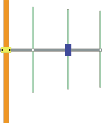
3 Elements VHF Yagi antenna

3 El VHF Yagi Antenna

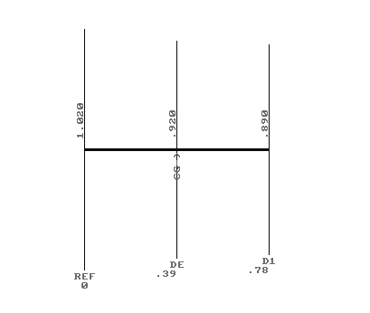
  FIG.1 shows a 3 elements VHF Yagi "homebrew" antenna designed with YAGIMAX 3.

FIG.1
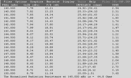
FIG.2 shows a table for the SWR, GAIN and F/B ratio.

VSWR_BW.gif - 28294 Bytes

FIG. 2

The maximum forward GAIN is about 8,17 DBi (6 DBd) on 145 MHZ. With 6 DBd (6 DBd = 8,15 DBi) gain, this antenna offering an Effective Radiation Power 4 times greater of the transceiver output (without Coaxial-Loss), i.e if you have a VHF transceiver with output Power of 50 Watts, your ERP will be multiplied 4 times = 200 Watts (in the forward gain direction). The antenna is compact enough (78 cm. Boom between Reflector-director) with excellent F/B ratio ( 20 DB) .

The Impedance on center frequency (145,000 MHZ) its 65 Ohms. If you connect a 50 Ohms coaxial cable directly to dipole, the SWR is 1.3:1

In practice the antenna needs a "matching system" for a 50 Ohms coaxial cable feeder ( H-100, RG-213 or similar) in order to minimise the SWR ratio to 1:1##

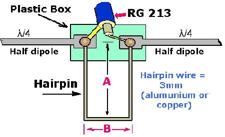
I have used a "Hairpin" system (FIG. 3), which is very simple and effective "matching method". YAGIMAX antenna design program including a calculation-tool for the Hairpin's dimension, depending on "Data" of the table above (FIG.2)

The Drive Element is an "Open - Dipole" (two pieces of about "Lambda/4") with overall length 0.92 m. (see FIG.1) FIG.3 shows the Drive-element (Dipole) and the Hairpin construction on the dipole's plastic box. Keep in mind, by using a Hairpin the dipole must be a bit-shorter than normal, in order to act as a capacitive-element (25.42-j31.62 at 145 MHz). Thus the overall length of dipole is about 92 cm.The space between the two screws is 2.2 cm (dimension B) and the dimension "A" is 5 cm for 1:1 SWR (on my antenna). If you have not the optimum SWR (1:1) we can increase (or decrease) the "A" dimension a few millimetres, looking for the minimum SWR.

dipol.gif - 5525 Bytes

FIG. 3

The antenna is being constructed by using 15 x 15 mm aluminium boom and I have used for the elements tubular aluminium rods of 8 mm diameter. If the elements are placed directly to the boom, without a plastic piece for isolation, the dimensions must be 5mm longer (Reflector = 1025 & director = 895). The plastic box which I have used for the dipole it was from an old TV-antenna.
*NOTE: if you place the antenna with Vertical polarization, the "center-cable" of Coaxial must be connected with the upper-section of dipole and the "shield" of Coaxial with the down-part of dipole.

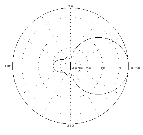
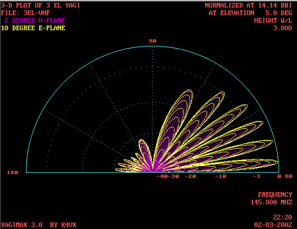
Finally, the FIG. 4, 5 shows the polar-plots of 3 Elements VHF Yagi.

*********

plot_copy1.gif - 4091 Bytes

FIG.4

3D_plot_copy.gif - 30513 Bytes