Thursday, 19 June 2014

THE PIPPIN QRP TRANSMITTER


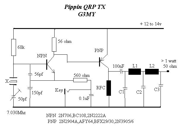
Basically, it is a conventional Colpitt type crystal oscillator but with the output taken from a low value collector load resistor and direct coupling is made into the base of the PNP device used as an amplifier. The result is a circuit even more simple than the OXO and with considerable advantages.

The small amount of forward bias developed for the PA stage makes it very much easier to drive but is less than the voltage required to actually bias the stage "ON". Keying is in the emitter circuit of the oscillator stage and when the key is up and no current is being drawn there is no forward bias at all on the PA stages.

The isolation of the PA from the oscillator by taking the drive from the low value oscillator collector load, is most impressive and there is virtually no pulling of the oscillator even if the PA load is briefly shorted to ground.

Input to the PA stage runs at 120 to 150mA. at 12 to 14 volts and output on 7Mhz runs at better than 1 watt measured into a 50 ohm load. The PA transistor has a "Stove Pipe" heat sink attached and has been left running continously for more than 1 hour without any complaint from the PA stage.The collector choke is the usual type and uses 6 turns of 29 swg on two ferrite beads in tandem.

http://www.qsl.net/g3pto/pippin.html

The NOGAnaut QRP Transmitter


The crystal oscillator is the simplest form of transmitter. Normally, oscillators are used to drive buffer amplifiers and power amplifiers, which provide increased output, as well as prevent the output circuit from adversely loading the oscillator.

Most transistors exhibit a characteristic impedance different from the 50-ohm impedance of a well-tuned antenna system. An improper match between the impedance of the transistor and the load (e.g. antenna system) can cause severe power degradation, and worse, can seriously affect the signal, including shifting the oscillator frequency in unpredictable ways.

In the NOGAnaut transmitter, the 2N2222A transistor, which exhibits a characteristic impedance of approximately 200 ohms, is matched to a 50-ohm load via the pi-network filter composed of C1, C2 and L2. The values of these components were chosen to provide a close match between the 200-ohm transistor and a 50-ohm antenna (it is therefore critical that a good 50-ohm antenna system be used with this transmitter). It so happens that these values also form the familiar half-wave harmonic filter, thus satisfying FCC spurious emissions requirements.

NOGAnaut Schematic

Figure 1. NOGAnaut 80M Transmitter Schematic.

Capacitor C5 provides the necessary feedback to begin oscillation. You may find that you can operate your NOGAnaut without this capacitor--stray capacitance in the circuit provides a certain amout of feedback without C5. However, it was found during development of this circuit that the oscillator can have troubles starting at times, therefore it is recommended that you leave C5 in the circuit.

The 0.01 uF capactor, C3, serves as a DC-blocking capactor. At 3.6864 MHz, this capacitor is essentially a dead-short to RF, but blocks the DC current from flowing into the load.

This is a familiar Colpitts oscillator, operated in "common-base mode." The usual base-bypass capacitor is replaced by the capacitance of the crystal. With a 15V supply, this transmitter has been measured to deliver as much as 134 milliwatts into a perfectly matched 50-ohm load ("your mileage may vary"). With a 9V supply, about 20-50 milliwatts should be expected.

The transmitter is keyed by interrupting the positive supply voltage. You can modify this to be grounded keying, if necessary (just interrupt the negative supply voltage instead of the positive voltage). This may be necessary if you use a keyer that expects grounded or negative keying.

For a very good description of crystal oscillators, check out Solid State Design for the Radio Amateur by Wes Hayward, W7ZOI, and Doug DeMaw, W1FB. This is one of the most popular amateur radio books ever written and is packed full of practical information about how solid state circuits behave. It is published by the ARRL, and can be purchased directly from them, as well as from many electronics retailers.

Further information about pi-network filters can be found in The ARRL Electronics Data Book, by Doug DeMaw, W1FB, also published by the ARRL. This book contains most of the nuts and bolts of basic circuit design, and is a must for any ham shack.

http://www.nogaqrp.org/projects/noganaut/circuitdescription.html
25 part transmitter for the QRP Minimal Art Session


My Minimal-Art-Session rig shown here was made for class B of theQRP-MAS competition which is in May every year. In class B the transmitter should have a maximum of 50 components, and the fewer the number of components, the more points one will get per contact. With such simple rigs, only CW is viable.

This rig was made by combining ideas from several designs that I had seen and it was finished the same day as the competition. I ended up with 22 components in the transmitter except for the output filter. The rules say that no matter what, the output filter counts as three components. I guess this is in order that no one is tempted to simplify the filter too much and start emitting harmonics. 

It was made directly on two experimental boards. The right-hand one is for the VXO and the PA and the left-hand board contains the output filter. The transmitter is housed in an enclosure which once was a network converter. The advantage was that there already was a BNC-connector and a power supply plug there. All the original surface mounted components were blown off with a hot air gun so that the original board could be used as a base for my boards.

QRP-MAS transmitter for 80 m with 25 parts, drawing by LA4YW, Liv

My transmitter is made to give as close as possible to the maximum power of 5 Watts, but I ended with 3.5 Watts even though the IRF510 is capable of more. But there was not enough drive signal for that. I also had some problems with high frequency oscillations so therefore there is a series resistor to the gate and some extra decoupling which raise the component count. The transmitter frequency can be pulled about 1 kHz for each crystal. I have used it with an antenna tuner and a 75 m horizontal loop and with my Elecraft K2 as receiver. Antenna switching was manual.  

I didn't really count on many contacts because I only had crystals for 3579 kHz, not for the QRP-frequency 3560 kHz. But surprisingly I had 6 contacts with D (Germany) and one each with ON (Belgium) and OK (Czech republic). The "best" rig component-wise that I contacted was DK0VLP with only 12 parts.

Next time I plan to make a tube transmitter - inspired by the AA8V/W8EXI One-Tube Transmitter - hopefully cutting the component count in two myself also.

Homebrewed Off-Center Fed Dipole


Ocfd.jpg

Building A Homebrewed Off-Center Fed Dipole Scanner Antenna.

Aluminum/copper tubing construction:

You will need to check the fit of the tubing with the T connector and the caps while you are at the store. One combination that fits nicely is 3/4" copper pipe with 3/4" CPVC fittings (not to be confused with 3/4" PVC fittings which will be too large). The tubing/connector is held in place with 2 stainless steel sheet metal screws for connecting the balun to each element.

Find a "U" bolt to fit your mast. Drill two holes in the support pipe to fit the U bolt.The support pipe is 18" from the "T" to the mast.

Remember, bandwidth increases as diameter of the elements increases. I think, if I remember correctly, at the hardware store, that a few CPVC fittings will fit copper tubing perfectly!

Some say that the 18" element on top mounted works best,Some like the 48" element on top.It does'nt matter,it works the same.

If you use the copper tubing,be sure to paint it with some good,non-conductive paint.I used to paint mine light grey. -Have fun! (Teraycoda)

For an alternate/temporary mounting option, drill a hole in one of the end caps and put in an eye bolt with a nut on the underside of the cap to secure. Be sure to secure this end cap to the copper tubing somehow, perhaps with an additional small stainless sheet metal screw. Be sure that the eye bolt itself doesn't make electrical contact with the tubing. Also, drill a small weep hole in the bottom end cap to allow any moisture to escape that may accumulate inside. Use the eye bolt and some rope to pulley the antenna up high in a tree, or use a hook to hang it somewhere. Give careful consideration to safety and grounding depending on your particular usage scenario. (Qdude)


Variation for Off-Center Fed Dipole Using Simple Wire and 75 to 300 ohm TV Balun Transformer

Offset dipole scanner antenna.jpg

Electrically, this version is the same as the one using copper tubing (above) but can be assembled quickly and is quite portable. While not as broadbanded as an OCFD using copper tubing or other metal with a larger diameter, the OCFD made from simple wire turns in great receive performance in all the commonly scanned bands, as reported here on RR in multiple message threads.

The legs/ends of the dipole are simple bell wire and shown here coiled up. Uncoil them and hang them vertically; doesn't matter if the long or short leg is at the top... works the same either way. The wire terminal lugs shown at the end of the legs of the dipole antenna should NOT be connected electrically to the wires - just crimp them on over the wire insulation. They are used as convenient hangers for the antenna, and not meant for electrical connection. Obviously, the lugs at the TV transformer/balun ends of the wire should be stripped before crimping on the terminal lugs to ensure contact with the antenna wires when you attach the TV transformer. Ensure the 75 ohm coax feedline that you connect from the balun/transformer runs away from the antenna at as near a 90 degree angle as possible.