Last year my cousin had to submit a class project towards her engineering degree and I suggested that a direct conversion receiver might be a good idea. This receiver is the result of that project.
Usual construction write-ups only deal with a finished design that is logically explained and the performance is discussed clinically. Such texts overlook the unpredictable path that an experimenter takes during a project. The final form is often a result of initial specifications, personal choices, accidents and availability of time and material.
Hence, this article: a journal that follows a receiver's birth. This receiver was made over several evenings, spending less than an hour each day.
For those real hams who never read the entire articles, I follow my convention of key caveats and some tips. Here is the entire circuit:

Remember this while assembling the receiver:
-
Shield the VFO. It should be inside a metal box. I soldered pieces of copper clad board (blank PCB material) around the VFO circuit.
-
I don't think you understood how important it is. So, I am saying it again, SHIELD THE VFO. This is a magic bullet cure for common ills of a direct conversion receiver.
-
The receiver layout is uncritical. But keep it clean. Q1, Q2 and Q3 form a tricky circuit. Double check the connections.
-
It might be tempting, but don't use a battery eliminator. It will produce hum. Use a regulated power supply with adequate filtering. A 15 volt supply with 2200 uF capacitor followed by a 7812 regulator is recommended.
-
I have included the voltages to be expected at all the transistor leads. Use that as a guide to trouble-shooting the receiver.
-
Double check the two transformer windings polarities.
-
Usually, the FETs have a very odd pin out, with the drain lead often put between the gate and source leads. Be careful and sure that you solder it correctly.
-
If the oscillator doesn't oscillate, swap the two ends of the VFO coil and try again.
Advice on building this receiver

This receiver is for someone looking for a weekend project. But it is quite a performer.
The receiver has just six transistors and a very common audio IC. You can substitute the audio IC with any other audio amplifier circuit. The oscillator too can be substituted by another design. A bipolar oscillator as a VFO (look at my BITX design) can be a lower cost substitute. The FET transistor used costs as much as all the other components put together. The entire receiver cost is still under Rs.100 (about two dollars) in India.
I have noted the voltages at all the transistor leads to help you trouble shoot your receiver. But don't be surprised if it works straight off. The only critical thing is to get the VFO inductance right. You can use another receiver to set it for proper coverage.
This receiver can be adapted to 80 meters as well as 30 meters. With some sort of VFO stabilizing scheme it can work on higher bands too. Nothing is sacred. Anything goes.
Why build a receiver?
Why do you want to build it? These are available at the Dubai Duty Free asked Harish, an old friend, when he spotted us struggling over the DC40 one evening. I didn't have an answer to this question and considering the amount of work piled this quarter, it appeared to be a sensible thing to ask.
I think this question is answered by us all in different ways. My personal answer would be because we human beings are fundamentally tool builders. We have an opposable thumb that allows us to grip the soldering iron.
For an engineer (by the word ‘engineer', I don't just mean those who have a degree, but anyone who applies technical knowledge to build things) the act of building a receiver is a fundamental proof of her competence and capability. It is much easier to put out 1 watt signal than it is to receive a 1 watt signal.
A simple definition of a good receiver is that a good receiver consistently, clearly receives only the intended signal, such a definition hides a wide range of requirements. The receiver has to be sensitive enough to pick up the weakest signal imaginable (note: clearly), it has to be selective enough to eliminate other signals (only), it has to be stable enough (consistently).
For a ham or an engineer, building a usable receiver is a personal landmark. It establishes a personal competency to be able to understand the very fundamental operation of the radio and mastery over it.
A direct conversion design
A direct conversion design is simple and pure. A signal arrives from the antenna; it is converted to audio by simply mixing it with a local RF source and played to your ears through an audio amplifier. The principle can be explained to anyone on a piece of paper in a few minutes. But having the principle expounded so simply, the issues of sensitivity, stability, dynamic range, etc. that confront a builder are exactly the same as those that will confront anyone building a far more complex system.
We chose a direct conversion design because:
-
It could be assembled easily from parts already available in the junk box.
-
A direct conversion receiver needs as much design consideration as superhet does to achieve acceptable performance.
-
I hadn't experienced a direct conversion receiver for a long time.
-
It would be an innovative project submission.
Initial Design
We didn't plan the receiver minutely. We knew that we required something like in the figure below:

So, the initial design was to fill up these four boxes in the following way:
-
RF Filter: Doubly Tuned Circuit centered at 7.050 Mhz
-
Product Detector: a two diode singly balanced detector
-
AF amplifier: discrete transistors used as audio amplifier to drive Walkman headphones.
-
VFO: Bipolar transistor based, low noise oscillator.
We reasoned that a doubly tuned circuit will prevent strong out-of-band signals from AM breakthrough. The singly balanced detector would be simply enough (just one trifilar coil to wind) and an audio amplifier based on discrete transistors would be better than the LM386 (that I was beginning to hate the LM386 for high noise).
Having read in the EMRFD (Ref. 1) that the local oscillator radiation can cause tunable hum and microphonics, it was contended that an RF amplifier might be required.
Day 1: Beginning at Audio End
We began the receiver construction by fishing out a copper clad board that was about 8 inches by 2-1/2 inches. Using an old razor blade it was scrapped until the copper looked bright. This was to be our new receiver's base.
We had decided to use discrete transistors in our design instead of the standard LM386. We fished around in the junk box for an NPN-PNP transistor pair to be used in the output stage. While looking around, an LM386 turned up. After a bit of head scratching, hate against the LM386 quickly gave way to an old familiarity. We decided to use the LM386 after all.
A few seconds on Google turned up the datasheet of the LM386. The LM386 comes in many flavors according to the datasheet, we were not sure of what the top operating voltage of our chip was (our version was not from National Semiconductors), so we decided to shoot for a conservative 6-9 volts range for our design. This was simply achieved by placing a resistor from the 12 volts supply line to the pin 6 (the power supply pin) of the IC.
We were not too sure of whether we required the additional gain required by adding a capacitor from pin 1 to pin 8: It was left out for the time being. The guiding principle being "Don't ask for more gain, unless you absolutely need". In any case, the extra gain, if required would be only a capacitor away.
It took us 15 minutes to complete the audio amplifier. We immediately wanted to fire up the amplifier. No suitable speaker was available. Looking around the shack, it was noted that the PC was hooked up to a Cambridge Sound Works' System. Those speakers were connected to their outboard amplifier using RCA jacks. One speaker was disconnected from the PC sound system, an RCA jack was soldered to the output of the amplifier.
Laziness took over, and the 12V power line was directly soldered to amplifier. Power was applied and a finger on pin 3 of LM386 produced a loud buzz (with a trace of the local AM station). It was alive. Pin 6 was expectedly hovering around 8 volts. A wet finger applied to the LM386's body revealed no heat. That wrapped up the initial tests of the audio amp.
To test it further, the output of the PC's sound card was soldered directly to the LM 386's input and the PC was booted. LM386 proved to be quite sensitive to the PC's output and the sound volume had to be cut down from the PC's end.
The evening ended with some Jim Morrison flowing out of the LM386. While the party mood had set in, the engineer in me realized that the pumping bass of Lonnie Mack on Roadhouse blues was intermodulating Robby Krieger's bluesy guitar. Note to myself: keep your eyes on the distort and your hands upon the gain!
Day 2: The Oscillator
The key issue plaguing us at this time was: what kind of tuning mechanism should we use? My junk box has a fast depleting stock of variable capacitors (just four more to go). On the other hand, varactor tuning would mean going out and buying a decent 100K linear potentiometer. Varactor tuning also adds noise to oscillator. It was decided to park this issue for the time being and get on with the rest of the oscillator.
A Hartley oscillator based on a FET was decided upon. It is easy to get a Hartley oscillator working. The numbers of crucial frequency determining components are few.
We started the work with winding a coil. A nylon tap washer was used as toroidal former to wind the oscillator coil. A toroidal coil's inductance in micro-henries is given as (k x square of number of turns). The k for these nylon toroids varies between 1nH per turns squared to 1.5 nH per turns squared. A coil with 80 turns (with a tap at 20 turns) was wound to give an estimated inductance of 3.6uH.
The oscillator was fabricated at the other end of the main board. Some space was left out to accommodate a big tuning capacitor if required. It was discovered that we didn't have a Zener diode or a voltage regulator chip in the junk box. We decided to go ahead without it for the time being. We didn't find a polystyrene capacitor either, so we used a disc ceramic 100 pf instead. To keep the circuit simple, an elementary emitter follower was used as a buffer to the VFO. The output of the emitter follower was hooked to an oscilloscope probe and power was applied to the VFO. No output was noted.
Power was removed immediately and the board was take out into the sun and examined carefully. Fortunately the Hartley is such a simple oscillator that one can easily visually verify the entire oscillator's connections. The board was brought back into the lab, power was applied again and the drain voltage was noted to be around 9 volts. The entire VFO was powered through a 470 ohms resistor. Hence a 6mA current appeared to be normal for the FET. The emitter follower was disconnected and the still no oscillations were observed at the FET's source.
At this time, just as I was fighting the urge to use the board as a projectile, the coil started looking suspicious as the rest appeared proper and the DC voltages around the oscillator appeared normal. It was decided to wind a new coil. This is an advantage of using the tap washers: They cost 50 paise each (about 1 cent) and you can throw away a bad one. A new coil was wound and soldered in. The old one's enamel was probably not scrapped well at the tap.
The oscillator was now working well. The output of the VFO was connected to a homemade frequency counter and the frequency was found to be around 5.5 MHz instead of 7 MHz. It was also noted that the oscillator was quite stable considering that the power supply to the VFO was not stabilized. The 100 pf tank capacitor was changed to 47pf to get the frequency down to 7.6 MHz.
An air variable capacitor was soldered across the coil with hookup wire to make it tunable. This made the oscillator unstable. Any hand movement near the VFO would make the frequency change. Even a light tap on the table would make the oscillator jump its frequency. It was clearly due to the variable capacitor's addition. The variable capacitors are quite temperature stable, and this behavior was probably due to the loose hook wires that connected the tuning capacitor to the oscillator. Clearly, we needed a front panel that would mount the tuning capacitor and hold it firmly. At this point, we declared the day close.
Day 3: The Box
It was decided that an air variable capacitor without a slow motion drive will be used to tune the receiver. A second piece of copper clad that was 8 inches by 2 inches (I got a large collection of them as discards from a local PCB making shop) was selected to be the front panel. Approximate location of the tuning capacitor was selected such that it would not cover the oscillator components and keep the shaft at mid height from the bottom of the panel to allow the biggest knob possible.
Using a hand drill, three holes were drilled for the tuning capacitor, the volume control and the ear-phones jack. The tuning capacitor required two screws to affix it to the panel, these were marked after inserting the shaft through the main hole and they were also drilled out. From a small piece of scrap copper clad board, three right-angled triangles about an inch to a side were cut and smoothened with a flat file. These were soldered in standing position on the main board and the front panel was in turn soldered onto these angles (see the pictures).
The main tuning capacitor was screwed in and so were the volume control and the phone jack. The oscillator was found to be oscillating at 7.6Mhz so a 22pf trimmer was added in parallel with the 47 pf to 'net' the oscillator at 7.000 MHz. Now the tuning range started at 7.0 MHz and went up to 7.5 MHz. This was quite a wide range especially because we were not using a slow motion drive. A 47 pf capacitor in series with the variable capacitor reduced the tuning range to 180 KHz. The oscillator was set using the preset to tune from 6980 to 7160 KHz.
Day 4: The audio pre-amp and the Big Bang
The W7EL (I am not sure if it is his original design, he is one of the most creative RF designers I have come across) audio pre-amp is now a classic. It consists of a common base stage biased at 0.5ma to give a 50 ohms input impedance that matches the output impedance of a diode product detector. This stage is directly coupled to a common emitter amplifier. Both these stages are powered through another transistor used as an active decoupler. The common base stage provides a stable 50 ohms matching impedance to the detector output, the active decoupler keeps power supply hum and noise out of this crucial stage and the second stage provides bulk of the gain.
We didn't have any text books at hand to refer to, so all we knew was that we should bias the first stage to 0.5mA current which we did and that the second stage should be biased well within the active region to handle at least a swing of 1V signal at the output. This is what we did achieve with the audio pre-amp. A 50 ohms resistance in series with a 0.1 capacitor was fashioned as 'pauper's diplexer' at the input of the audio preamp. The diplexer is supposed terminate all frequencies above the audio range that could come out of the diode mixer.
Now, we had everything in except the diode mixer in place. We couldn't wait to get the first noise out of the receiver. So we hastily slapped together a two diode mixer (singly balanced), connected it to the oscillator, hooked up the audio chain, tack soldered a single piece of wire from the 20 meter dipole's coax to the center tap on the diode mixer and powered the receiver on.
We well did receive - a number of AM stations. Tuning the receiver around resulted in whirrs and whooshes, some of them distinguishable as RTTY stations and some constant carriers. There was a strong hum-like noise across the band.
Until now, our progress was more or less smooth, our performance problems were quite distinct and their solutions quite distinct. But our current problems were not easily measurable and 'knowable'. All we knew at this point was that the receiver was not receiving.
I suggested two things. First, introduce some selectivity in the front-end. Second, get a known signal that you can tune to.
We quickly fashioned a coil and cap tank for the front end that was coupled lightly through 22pf capacitors to the antenna lead and the diode mixer. A 7050 MHz crystal was soldered into a test oscillator and used as a signal generator.
We found that we could tune in the signal. So the receiver was basically working. At this point, my cousin was losing courage. This was not the way she saw it. From her point of view, we had designed and build the circuit. All blocks were working as expected but due to some evil spirit we were not having a working receiver.
At this point, we decided to sleep over the problem and revisit it the next day. We needed a plan for the next day to keep the spirits up.
Day 5: Completion
Our problems were clearly centered around our product detector, we decided to do something about it. It could have been any of the following:
-
Insufficient drive from the VFO: We had a simple emitter follower as a buffer to the oscillator. The oscilloscope showed that it had insufficient bias and it was clipping on the down-swing.
-
Singly balanced: The RF input was not being balanced out at the detector output. We needed a doubly balanced detector.
-
According to Rick Campbell's texts, VFO leakage into the RF input is responsible for tunable hum and microphonics.
A trip was made to the market and 9.1V Zener was procured that was soldered between the power line of the VFO and the ground. The supply resistor was changed from 470 to 220 ohms so that the Zener had reasonable bias current.
The VFO's buffer amplifier was changed from the skimpy single stage design to using a two stage amplifier with feedback with unity gain and the VFO was completely shielded from all sides by soldering copper clad boards all around it. (See the pictures).
A doubly balanced detector was fabricated using two trifilar coils and four diodes. A simple diplexer of a 0.1uf in series with a 50 ohms resistor was added to the detector output to properly terminate the mixer.
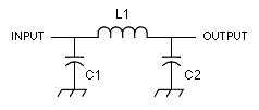
A simple low pass filter was added on a trial basis to the input of the detector. The receiver was fired up.
Success at last! The receiver was now working just as well. Connected to a long wire (actually, the shield end of the 20 meters inverted V), it pulled signals from all around. The noise floor was sufficiently low to mark a dramatic jump in the noise when connected to the antenna.
Performance
We do not have the tools to make performance measurements on the receiver. Hence, we rely on our actual receiver experience instead. The receiver is clearly far more sensitive than is required for this band.
We used a regular disc ceramic capacitor in the VFO, but still, it is quite stable. The local SSB nets could be monitored continuously without needing to retune. Even the initial warm-up took less than a minute and the drift was less than 1 KHz during this period (not measured).
The initial audio bandwidth was much greater than 3 KHz. A 0.1 uF at the output of the audio preamp brought the band-width down to acceptable levels. Ideally, an active first or second order low pass filter based on op-amps should have been used. However, the current arrangement is sufficient for us. I personally prefer a wider than normal bandwidth.
At rare instances, a slight trace of AM breakthrough can be heard, if we had an RFC, we could have inserted it between the AF amplifier and the detector to keep the RF out of audio stages. The AM breakthrough, when it happens, it hardly perceptible and it takes a bit of concentration to discern it above the band noise.
Conclusion
We had started with an over-engineered design that included an RF amplifier, etc. Our first cut was a sub-optimal design, and the final version was a reasonable compromise between performance, effort and component availability.
The receiver performance is very clean and the stability is quite good, it is now the standard night-stand receiver by the bed.




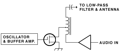
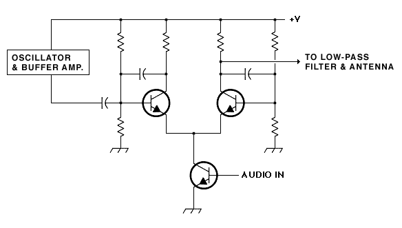
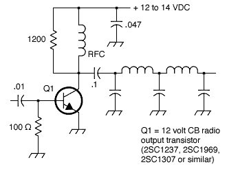
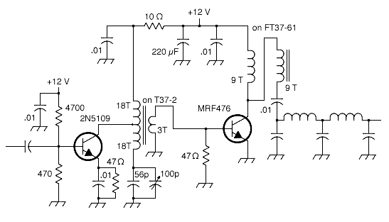
![[diagram]](http://www.geocities.ws/raiu_harrison/mwa/tech/circuits/oscxtal1.gif)
![[diagram]](http://www.geocities.ws/raiu_harrison/mwa/tech/circuits/osclayo.gif) If you've never built a circuit from a schematic before, this might be a good one to start with. The diagram below shows how you can arrange the parts on a prototyping board such as Radio Shack catalog number 276-175. (A prototyping board, also called a solderless breadboard, contains groups of holes that are electrically connected. Each hole has a little spring/clamp thingy in it that grabs ahold of the component leads. This is a great way to experiment with circuit designs and learn about the building process.)
If you've never built a circuit from a schematic before, this might be a good one to start with. The diagram below shows how you can arrange the parts on a prototyping board such as Radio Shack catalog number 276-175. (A prototyping board, also called a solderless breadboard, contains groups of holes that are electrically connected. Each hole has a little spring/clamp thingy in it that grabs ahold of the component leads. This is a great way to experiment with circuit designs and learn about the building process.) ![[diagram]](http://www.geocities.ws/raiu_harrison/mwa/tech/circuits/oscxtal2.gif)
![[diagram]](http://www.geocities.ws/raiu_harrison/mwa/tech/circuits/oscxtal3.gif)
![[diagram]](http://www.geocities.ws/raiu_harrison/mwa/tech/circuits/oscxtal4.gif)
